

OrthoOsteotomy


OrthoOsteotomy helps trained orthopedic professionals review lower-limb osteotomy geometry on a user-selected X-ray
in a spatial Apple Vision Pro workflow.
Load an authorized X-ray or training image, calibrate scale with C1/R2, place the ordered anatomical landmarks P1-P9,
and review geometric overlays directly on the X-ray board. The app displays construction lines, point labels,
mechanical-axis helpers, joint-orientation values, Fujisawa target visualization, hinge-point and wedge-base planning
support, and alpha/beta/delta/omega outputs for professional review.
The workflow includes guided help for landmark placement, a 2D measurement board, optional immersive board
visualization, optional Muse spatial-stylus input, zoom and view controls, undo support, and user-controlled local
JSON/CSV export. In Muse mode, the live projected aim is shown as a separate crosshair; a smaller transparent point
sphere appears only after the user commits a point.
Designed for trained healthcare professionals, orthopedic education, research, and authorized institutional workflow
validation.
Important clinical notice: OrthoOsteotomy is a planning-support and educational tool. It is not for primary image
interpretation, does not dispense medical advice, and does not replace professional clinical judgment, institutional
validation, or legally required regulatory clearance. All information received from the software output must be clinically
reviewed regarding its plausibility before patient treatment. Measurements depend on image quality, calibration accuracy,
landmark accuracy, Muse projection accuracy when used, user technique, and independent review.
 |  |  |  |
|---|---|---|---|
 |  |  |  |
WHAT THE APP DOES
OrthoOsteotomy is a professional planning-support and educational workflow tool. It allows authorized users to load an
X-ray image, place landmarks in a prescribed sequence, calibrate measurements, visualize lower-limb alignment geometry,
and review calculated geometric suggestions that must be independently checked by a qualified clinician.
The app supports:
- ordered landmark capture using the preserved osteotomy workflow
- scale calibration using C1/R2 or another known reference
- mechanical-axis and joint-orientation review
- Fujisawa target selection and visualization
- hinge-point and wedge-base planning support
- 2D board review and optional immersive spatial review
- optional Muse/spatial-stylus board projection
- local JSON/CSV export selected by the user
BASIC WORKFLOW
1. Open OrthoOsteotomy.
2. Review the clinical responsibility notice.
3. Load an authorized X-ray or training image.
4. Calibrate the image by placing C1 and R2 and entering the known reference size.
5. Place P1-P9 in the guided order.
6. Review the measurement panel and help explanations.
7. Select the Fujisawa target and review the projected mechanical-axis line.
8. Place H and D for hinge and wedge geometry review.
9. Use alpha/beta/delta/omega and DD' outputs only after independent clinical plausibility review.
10. Export only when authorized.
POINT REGISTRATION MODES
Default board pointer:
Use the concentric-circle pointer/crosshair over the X-ray board. Move the center of the pointer to the intended landmark
and use the app confirmation gesture to register the next ordered point. Use Undo if the point is wrong.
Optional Muse spatial stylus:
If available and enabled, the Muse crosshair is projected onto the board. Distal/tip or primary commits the board
projection. Proximal/secondary undoes the last point. A quick repeat distal/primary press over the same just-placed point
can also act as an undo fallback when the hardware/OS reports buttons inconsistently. If the Muse pointer, button
recognition, haptic response, or projection is unreliable, use the default board pointer workflow.
TROUBLESHOOTING
Cannot load an X-ray:
- Confirm Photos/File access permission.
- Use a standard JPEG or PNG training image.
- Avoid very large images if device memory is limited.
- Restart the app and try again.
Calibration looks wrong:
- Confirm the calibration object size.
- Place C1 at the center and R2 at the reference edge/radius point.
- Recheck whether the app expects cm or mm in the current entry mode.
- Recalibrate before trusting any distance output.
Points are not placed where intended:
- Zoom and pan the X-ray before placement.
- Use the pointer/crosshair center, not the edge of the pointer.
- Undo and repeat the point.
- If Muse input is active and unreliable, switch to default pointer placement.
Immersive board is hard to use:
- Adjust board width, distance, and height.
- Keep the 2D board as the measurement source of truth.
- Use the immersive board as a visualization and input aid only.
Support request:
Email info@orthopractis.com. Please include:
- App name and version.
- Device model.
- visionOS version.
- Whether the issue occurs on simulator, Apple Vision Pro, or another device.
- Whether optional Muse input is enabled.
- Exact steps needed to reproduce the issue.
- Screenshots or screen recordings that do not contain protected health information.
- A de-identified training image only if necessary and authorized.
DO NOT SEND PROTECTED HEALTH INFORMATION UNLESS AUTHORIZED
Do not send patient names, dates of birth, hospital IDs, identifiable X-rays, or other protected health information to
support unless your institution, patient consent, and applicable law authorize it.
OrthoOsteotomy is intended for trained healthcare professionals and authorized educational/research users. It is not a
substitute for professional clinical judgment, institutional governance, or legally required regulatory clearance. All software
output must be clinically reviewed for plausibility before any patient-care decision.
The app preserves the ordered osteotomy landmark workflow in way accorndingly the gif that are also presentd for help durin g selection of point
Calibration:
- C1/R2: known calibration reference.
Anatomical landmarks:
- P1: femoral head center.
- P2: greater trochanter / proximal femoral reference.
- P3: femoral canal center reference.
- P4-P5: distal femoral condyle points / distal femoral joint line.
- P6-P7: proximal tibial plateau points / tibial joint line.
- P8-P9: distal tibial / ankle reference points.
- H: osteotomy hinge or apex point.
- D: osteotomy starting/base point.
- D': simulated or manually adjusted corrected point where available.
Use rule:
The user must place points in the guided order. Incorrect point order or inaccurate placement invalidates downstream
geometry. Use Undo and repeat when a point is wrong.Please understand the gifs
================================================================================
7. MEASUREMENT FAMILIES AND CONSTRUCTION
================================================================================
This app displays geometric outputs for professional review. The exact UI names may vary by build, but the measurement
families are:
1. C1/R2 calibration
Meaning:
Defines the scale for metric output.
Construction:
User places C1 and R2 on a known reference and enters the real-world size.
Planning use:
Converts board pixel distances to mm or cm.
2. MAD - Mechanical Axis Deviation
Meaning:
Deviation of the mechanical axis from a knee-center or reference point.
Construction:
Mechanical-axis line is derived from femoral head/hip region and distal tibial/ankle reference points. The app displays
deviation relative to the knee region/reference line.
Planning use:
Varus/valgus alignment review and target-line visualization.
3. mLDFA - Mechanical Lateral Distal Femoral Angle
Meaning:
Distal femoral orientation relative to femoral mechanical axis.
Construction:
Femoral mechanical axis and distal femoral condylar line P4-P5.
Planning use:
Femoral source review.
4. JLCA - Joint-Line Convergence Angle
Meaning:
Angular relationship between the distal femoral joint line and proximal tibial joint line.
Construction:
Line P4-P5 compared with line P6-P7.
Planning use:
Joint-line/soft-tissue/laxity review and optional JLa adjustment.
5. mMPTA - Medial Proximal Tibial Angle
Meaning:
Proximal tibial orientation relative to tibial mechanical axis.
Construction:
Tibial axis and tibial plateau line P6-P7.
Planning use:
Tibial source review.
6. HKA / limb-axis values
Meaning:
Global hip-knee-ankle alignment review.
Construction:
Femoral head/hip reference, knee reference, ankle/distal tibial reference.
Planning use:
Global limb alignment screen and before/after planning-support review.
7. MJL / KAO / related joint-line values
Meaning:
Mid-joint-line and knee-axis orientation values depending on the selected workflow.
Construction:
Derived from condylar/plateau landmarks and limb reference lines.
Planning use:
Joint-line obliquity and alignment review.
8. Fujisawa target
Meaning:
User-selected target position across the tibial plateau.
Construction:
Target point is positioned along the tibial plateau reference according to selected Fujisawa percentage.
Planning use:
Mechanical-axis target visualization.
9. H/D/DD'/alpha/beta/delta/omega
Meaning:
Hinge and wedge geometry family for planning-support visualization.
Construction:
H is hinge/apex. D is starting/base point. D' is simulated or manually adjusted corrected position. HD is osteotomy
width; DD' is wedge height; alpha/beta are angular controls; delta/omega are biplanar resultant outputs.
Planning use:
Review of wedge geometry and combined coronal/sagittal correction suggestions.
================================================================================
8. ALPHA, BETA, DELTA, OMEGA, AND DD' MODEL
================================================================================
Definitions:
- alpha (α): coronal correction angle.
- beta (β): sagittal or slope correction component.
- delta (Δ): resultant biplanar correction angle.
- omega (ω): direction/orientation of the resultant correction plane.
- H: hinge/apex point.
- D: starting/base point.
- D': planned corrected point.
- HD: osteotomy width from H to D.
- DD': planar wedge opening or shift.
- ΔDD': wedge-height effect from the resultant biplanar angle.
Legacy-style mathematical logic:
- Δ = atan2(tan(α) x tan(β), sqrt(tan²(α) + tan²(β)))
- ω = atan2(tan(α), tan(β))
- If α = 0 and β != 0, Δ = |β| and ω = 90°
- If β = 0 and α != 0, Δ = |α| and ω = 0°
- ΔDD' = 2 x HD x sin(Δ / 2)
Implementation caution:
Mathematical values should be verified against the original clinical workflow, expected coordinate conventions, side
selection, sign convention, and institutional method. The app displays values as planning-support suggestions, not as
standalone clinical decisions.


How to measure
Planning osteotomy
Prerequisites for the planning process are good quality whole weight-bearing x-ray of the entire lower extremity and knee lateral x-ray in case tibial slope is planned to correct. A circular (i.e. metallic sphere or coin) of known dimension object (calibration marker) have to be placed adjacent patients body before and included in patients x-ray.
Calibration procedure.
Once you load the app you have to open from photo library or capture the corresponding image from camera Calibration unit box in mm have to be filled according to known dimension of calibration marker included in X-ray image. If the - i.e. a 10 mm circular object appear, a 10 value is added to unit box.
Aiming the transparent circular yellow template over the circular x-rayed objects contour and fitting the best-fit circle to the contour of the circumferences of the calibration marker, user should click the “point” button, by this the center of the calibration marker is marked and sequentially a dynamic circle appears over the screen. The radius of the circle is dynamically changed whenever users finger is moved over screen. Once best fit of the radius of dynamic cycle over the contour of the calibration object is reached user should press the “point” button and circle with the respective radius point is drawn over image. By finishing the calibration procedure the app can measure dimensions in mm. It is strongly recommended to calibrate the app and insert the respected value in unit box in order to have accurate measurements otherwise software backtracks and it is not allowed to proceed to next stepson error message is appearing. In a calibration marker does not exist in image please use the medullary canal of the femur and have an approximate arbitrary value of 15 mm measured at the widest part of the canal.
Point Registration
Next with the transparent circular template user aims to locate the center of the femoral head. By fitting the best-fit circle to the contour of femoral head circumference and clicking the “point” button the center of the femoral head is marked (P1). By the same manner the medial side of the tip of the femoral great trochanter is marked (P2), likewise by aiming the intramedullary femur canal the center of intramedullary femoral canal (P3).
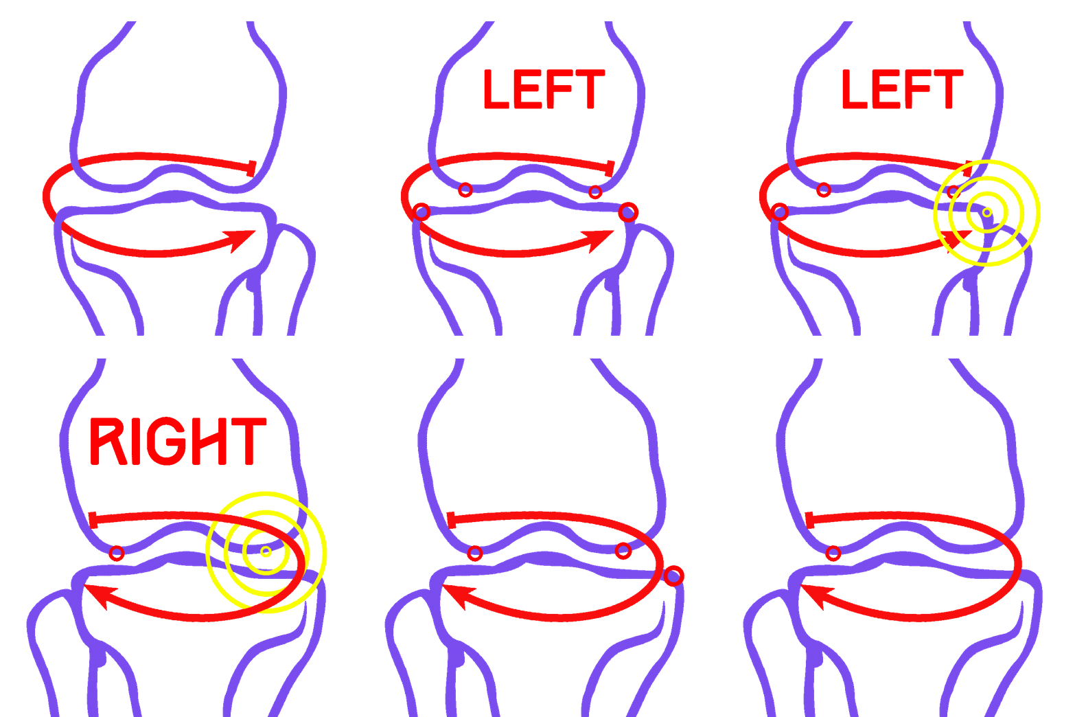
In case the right limp is measured the user should select the following anatomical points sequentially in certain clock-wise fashion starting from the most distal and lateral point of lateral femora condyle (P4) to most medial and distal point of medial femur condyle (P5) (please see tutorial gifs) to the most medial and proximal tibia point (P6) to most lateral and proximal tibia point (P7). By the same manner for distal right tibia user the select most lateral distal point of tibia at ankle joint or most lateral proximal over talus in ankle joint (P8) and most medial distal point (P9) of tibia at ankle joint or most medial and proximal over talus in ankle joint. (right limp clock-wise).
I case left limp is measured the above pattern should be followed likewise but the points should be selected in counter-clockwise fashion. (please see tutorial gifs)
Measuring the mechanical axis deviation (MAD) -orange line - in millimetres that is the perpendicular distance from the center of the knee joint to the mechanical leg axis to the knee joint center. This line physiologically runs on average 4 (±2) mm medial to the center of the knee joint. If the mechanical axis runs lateral by > 10 mm or > 15 mm medial to this point, this indicates either a valgus or a varus deformity of the respectively
Selection of mechanical axis at Fujisawa Point.
The mechanical axis of the leg, should pass normally at Fujisawa point (F) which is usually located at 12 % lateral of the center of tibia plateau. A blue line is drawn from femoral head centre (P1) to the Fujisawa point (F) at center of the tibia plateau which by default is set at 0% between the medial and lateral border of tibial plateau. By pressing + or - button the blue line with center the femoral head is rotated clock wise or counter clockwise intersecting the tibial plateau at Fujisawa point (F) while the respective percentage appears over the button. By this way the planned mechanical axis can be changed in real-time and pass according to user preference at the corresponding percentage at tibia plateau. By evaluating the residual cartilage thickness left on the involved tibia plateau compartment the percentage could be selected. User can select values between 0 % to 35% according to residual cartilage evaluation, by pressing + or - button respectively. In case one third of the cartilage thickness is left on the medial compartment, the mechanical axis should pass at 20–25 % on lateral compartment on the Fujisawa scale, or in case no cartilage is left then at 30–35 % and in case two thirds of cartilage remains at 10-15% respectively.- in case the no selection is done the percentage remains to default value at 0%.
Kind of osteotomy
The preoperative planning method can be applied to both closed- and open-wedge osteotomies. (HTO -high-tibial osteotomy, DFO -distal femur osteotomy) Helps to normalize knee joint angles and the orientation of the mid-joint line.
Traditionally the corresponding opening height of the osteotomy which the depends on the determined opening angle and the length of the osteotomy cut (mediolateral diameter of the osteotomy) can be derived from Hernigou’s trigonometric chart. App calculate the corresponding opening height of osteotomy helping the surgeon to avoid this cumbersome manual procedure.
First , Selection of hinge point of tibia or femur osteotomy-calculation of correction angle in frontal plane .
User can select the location of hinge point of correction osteotomy for planning of varus or valgus corrections of the distal femur (above mid joint line, distal femur osteotomy DFO) or proximal tibia (below mid joint line)
high-tibial osteotomy HTO), lateral or medial, closed or open - wedged.
By aiming with circular centred pointer below mid joint line at the preferred side of tibia (high-tibial osteotomy HTO) and by pressing the point button user can define the hinge-point of osteotomy (H) at tibia.The angle formed by red lines connecting the hinge-point (H) with the current center of ankle and the intersection of the projected Fujisawa line (blue line) to projected horizontal line of the center of ankle is the angle of correction (a).
By aiming with circular centred pointer above mid joint line (distal femur osteotomy DFO). The angle formed by red lines connecting the hinge-point (H) with the center of femoral head (P1) and the intersection of the line passing from selected Fujisawa point line and current center of ankle to projected horizontal line of the center of femoral head (P1) and the trochanter major (P2) ankle is the angle of correction (a).
The angle (a) is transferred to the level of the planned osteotomy and in case of ligament laxity JLCA >2 degrees (JLCA = joint line convergence angle, normal value 0-2°) the correction angle (A) is adjusted as follow- A = correction angle adjusted and presented on screen as JLa =a- (JLCA-2/2).
While user aims to realigning the mechanical axis to its anatomically normal position by changing the angle of correction in a real time simultaneously a simulation of the osteotomy is depicted by the wedge intended osteotomy and meanwhile all parameters in real time are being updated .
Second Starting point of osteotomy (D).
By aiming at the preferred side across the H point over the other side of the bone with the circular centred pointer and by pressing the point button, the surgeon selects the entry point starting the opening or closing wedge osteotomy.
From point H to point D, the mediolateral diameter the opening or closing of the osteotomy is printed (HD) in mm and marked by a red line, which represents one plane of the triangular wedge of the osteotomy.
The + or - button appear at the left bottom corner of the screen. Over the button the degrees of correction also appear - default value is 0 ° - for every click by pressing + or - button, one degree of correction is added or subtracted respectively and the second plane of osteotomy emerges and printed in screen as second red line (HD`) from H point to point D`. All previous measured values and location of drawn lines are being updated in real time accordingly till the orange line mechanical axis attach the corrected mechanical axis passing at Fujisawa Point.
The H point represents the hinge point of osteotomy and the tip of the wedge triangle. The planes of the osteotomy HD and HD` form the angle which is the actual correction angle of the wedge. The base of the triangle (DD`) the lateral cortex corresponds to the height of the wedge. By pressing the + or - button, with center the hinge point either clockwise or counter- clockwise, the corresponding height (DD`) of opening or closing osteotomy is increase or reduced respectively. Both proximal tibial head osteotomies (HTO = high-tibial osteotomy) and supracondylar femoral osteotomies (DFO = distal femur osteotomy) can be performed in additive technique (open-wedge) or subtractive technique (closed-wedge) and can be planned.
This powerful features allow surgeon in an instant to comprehend in real time by updating simultaneously all relevant parameters by changing the correction angle and thus helping to differentiate between a femoral and or tibial cause of deformity and avoiding osteotomies that could worse joint obliquity. By pressing the undo button user can easily return to previous stage and modify the selection of points or change the above mentioned parameter respectively.
The real time dynamically change of mechanical axis lines, modify also the drawings of femur and the tibia and in instant depicting a precise preview of the whole preoperative plan for optimal results.
The categorisation of the deformities based to international literature normal references values, help to indicate to user the type of osteotomy.The real time kinematic evaluation done after correction of the deformity assist in real time the optimal angle selection for uneventful correction of deformity taking into account all factors that potentially affect the end result.
Biplanar osteotomy, and Sagittal plane correction -Tibial slope (β angle ).
By taking lateral x ray of tibia and measuring the tibia slope the surgeon can correct the deformity not only at coronal plane (valgus/ varus, a angle but also in sagittal plane (biplanar osteotomy- combined correction) by increasing in open wedge osteotomy or reducing in closing wedge osteotomy the tibia slope angle. In the tibial slope box (β box) angle user enter the degree of correction namely the absolute difference between current measured profile X-ray and the planed - in case the field in box is left empty - default value is 0°, no correction at sagittal plane - in other words the osteotomy will correct only at coronal plane (varus-valgus -a ) the deformity thus ω angle is 0° and δ angle is also 0°.
In case, the tibia slope should be reduced user has to plan only open wedge osteotomy and simply to add the preferred absolute value of correction in tibia slope box β ,(i.e. measured tibial slope 4°- normal value 10°- the absolute amount of correction is the difference namely 6° and this value should be inserted in tibia slope box). In case the tibia slope should be increased a closed wedge osteotomy should be planed with the hinge chosen across to the other side of tibia and the direction of osteotomy (ω) should be the same amount bunt counterclockwise this time.
Delta (Δ) angle for open or closed osteotomy, the corresponding omega (ω) angle, the height of opening or closing osteotomy δDD’ are being calculated in real time. Negative values in tibia slope box does not affect the end
To avoid overcorrection especially during exaggerated joint laxity correction angle a is adjusted by taking into account ligament laxity measured by joint line convergence angle (JLCA) the JLa joint ligament adjusted angle is measured by the following mathematical formula (JLa = a - JLCA-2/2 - if JLCA>2) this could be helpful in surgeon who wants to correct the deformity by taking in to account the ligament joint laxity .
The selection of the amount of correction should based over the experience to avoid over or under correction .
The App helps to categorize objectively deviation or deformity in the frontal plane (varus or valgus) and differentiate the level of deformity (femoral and or tibial origin) and according to measured angles objectively suggest where indicated, medial or lateral, open or closed-wedge distal femur osteotomy or high-tibial osteotomy or double osteotomies. Restoring the mechanical axis by osteotomies around knee is easily calculated and presented on screen. In addition by measuring Hip Knee Ankle line (HKA) and Mid joint line (MJL) orientation, App allows to evaluate in real time the success of intended osteotomy by evaluating the kinematic alignment of the knee (KAO), avoiding residual joint obliquity or malalignment.
In case femoral angle (mLDFA) and tibial angle (mMPTA) and Hip Knee Ankle line (HKA) and Mid joint line (MJL) are in abnormal range double osteotomy is suggested and which kind of double osteotomy is indicated also
In case femoral angle (mLDFA) or tibial angle (mMPTA) abnormal ,Single osteotomy is suggested.
Outcome of planned degree of correction is also presented and a green coloured message of successful osteotomy is presented on screen in case femoral angle (mLDFA) and tibial angle (mMPTA) and MJL normal HKA normal otherwise with a red message appears not successful osteotomy
In quick review:
The following points at certain anatomical landmarks should be sequential selected and registered by pressing “point” button.
Calibration procedure
C1 → center of a known dimension object.
R2 → dynamic cycle radius of the known dimension calibration object ( coin metallic sphere - e.g. for 10 mm, enter in unit box the value 10 )
The following point should be registered at femur and tibia after calibration
For right limp in clock wise fashion during point selection at knee joint and around the ankle. For left limp the points are counterclockwise selected.
C1 → femoral head center
T2 → tip of trochanter majo,medial ridge.
P3 → center of intramedullary femoral canal preferably at mid-shaft
P4 → most distal, lateral femur condyle.
P5 → most distal, medial femur condyle.
P6 → most proximal, medial tibia condyle.
P7 → most proximal lateral tibia condyle.
P8 →most distal lateral tibia
P9 →most distal medial tibia
F → the location of Fujisawa Point (F) is adjusted. Blue line is moving and passing at the intersection to Fujisawa Point (F) over tibia plateau by pressing + or - button in the respected percentage lateral or medial is chosen - default value is 0 %, passing from the middle of tibial plateau. According to
residual cartilage left at the affected side -> blue line -planned mechanical axis- should pass at F point at following percentage indicated at table below
Two third- -> 10–15 %
One third ->20–25 %
None -> 30–35 %
Selection remains surgeon preference.
H → hinge point of the osteotomy wedge.
D → across the H point to the other side of the bone-the opening of the wedge.
Final degree of correction - default value is 0 ° - for every click by pressing + or - button, one degree of correction is added or subtracted respectively and the second plane of osteotomy emerges and printed in screen as second red line (HD`) from H point to point D.
a → final opening or closing correction angle, value is changed according to final planned osteotomy in real time. By observing the continuously calculated messages below or above in real time surgeon can choose the final degree of correction a till the simulated osteotomy is successful.
[a] → initial calculated opening or closing correction angle.
In case left limp is measured the above pattern should be followed likewise but the points should be selected in counter-clockwise fashion.
Before selecting a point a the tutorial gif is played to assist the user accurately.
By pressing ? Button - help menu - and by pressing the help on off button, user can optionally select to switch off or on the tutorial gif presentation help - default value on .
screen contents is saved as an image to the photo album of the device.
Unit box, a know - i.e. a 10 mm circular object included also in X-rays user should type the number 10 in unit box. In case box is left blank measure in mm is not possible and an error message is presented.
β angle -tibial slope box -the preferred absolute value of correction in tibia slope in sagittal plane.
Screen readings:
Arrows pointing up above normal arrow pointing down below normal
mLPFA = mechanical lateral proximal femoral angle, normal value 90° ± 5°, yellow
mLDFA= mechanical lateral distal femoral angle, normal value 87° ± 3°, orange
aLDFA = Anatomical lateral distal femoral angle, normal value 81° ± 2°,green
aMFA = anatomical mechanical femoral axes angle, normal value 6° ±1°.
JLCA = joint line convergence angle, normal value 0-2°. Light blue
d= distance in mm between femoral joint center and tibia joint centre normal values <=6mm, subluxation due to ligament laxity
mMPTA = mechanical medial proximal tibial angle, normal value 87° ± 3°, brown.
mLDTA= mechanical lateral distal tibial angle 89 ° ± 3°, blue
aFTA = anatomical femorotibial angle, standard value 173-175°.
MAD = mechanical axis deviation in mm.
Type of deformity
normal no message ,
femoral (mLDFA ≥ 87° ± 3°) varus otherwise valgus, deviation or deformity,
Tibia (mMPTA ≥ 87° ± 3°) valgus otherwise varus , deviation or deformity,
differentiate between a femoral and a tibial cause of malalignment
Genu varum, Anatomical femorotibial angle(aFTA) > 173–175° and
Mikulicz line runs medial to the 4 mm point, significant in MAD > 15mm medial to the center of the knee joint
Genu valgum, Anatomical femorotibial angle (aFTA) < 173–175°
Mikulicz line runs lateral to the 4 mm point, significant in MAD > 10 mm lateral to the center of the knee joint
FL=femoral length in cm
TL=tibia length in cm
LL’=Mechanical Axis length in cm
HKA =Hip Knee Ankle line, normal range 180 ° ± 3° otherwise knee <177° varus valgus >184
MJL = Mid joint line orientation (normal 87° - 94°, varus<86 ° valgus >94 °
KAO=Kinematical Aligned Osteotomy, normal if HKA and MJL are normal, otherwise abnormal.
a =final opening or closing correction angle in coronal plane.
[a] → initial calculated opening or closing correction angle in coronal plane
JLa = correction angle adjusted by taking into account ligament laxity measured by joint line convergence angle (JLCA)
JLa = a - JLCA-2/2 - if JLCA>2
HD= initial plane of triangular, mediolateral diameter the opening or closing of the osteotomy in mm
DD`=base of the triangle, or osteotomy gap opening or closing in mm adjusted by trigonometric chart of Hernigou, needed to obtain the desired angular correction at coronal plane -at a angle .
Δ angle = correction angle at ω plane
ΔDD´=base of the triangle, or osteotomy gap opening or closing in mm adjusted by trigonometric chart of Hernigou for Δ angle .
ω angle =direction of osteotomy plane. In case ω angle is 0° the osteotomy is directed perpendicular to sagittal plane and only in the coronal plane the deformity is corrected. By default ω angle is 0°
.
Outcome: Successful osteotomy if femoral angle (mLDFA) and tibial angle (mMPTA) and MJL normal HKA normal otherwise with red not successful osteotomy
Suggested osteotomy
Osteotomy suggestion: Single osteotomy, distal femur osteotomy (DFO) or high-tibial osteotomy (HTO) - Medial or Lateral open or closed wedge accordingly or double osteotomy both distal femur osteotomy (DFO) and high-tibial osteotomy (HTO) Medial or Lateral open or closed wedge
orange line = current mechanical axis of the leg.
blue line- Fujisawa line = Corrected mechanical axis passing at Fujisawa point.
All information received from the software output must be clinically reviewed regarding its plausibility before patient treatment! App indicated for assisting healthcare professionals. Clinical judgment and experience are required to properly use the software.These instructions alone do not replace in depth training in planning for osteotomies. It only serves as a general guideline.
Any influence the operators in making decisions during operation remains Surgeons own responsibility and experience. A surgeon must always rely on his or her own professional clinical judgement when deciding whether to use a particular technique when treating a particular patient. App does not dispense medical advice. The software is not for primary image interpretation. It is recommended that surgeons must be trained in the use before using it in real surgery.
OrthoOsteotomy is a local-first spatial X-ray landmark and osteotomy geometry support app for trained healthcare
professionals, orthopedic educators, research teams, and authorized institutional users.
The app lets the user select an X-ray or training image, calibrate scale using C1/R2, place ordered landmarks P1-P9
plus H and D, and review geometric overlays and measurement outputs such as MAD, mLDFA, JLCA, mMPTA, HKA,
MJL, Fujisawa target position, alpha, beta, delta, omega, DD', and delta DD'.
The app is not for primary image interpretation, does not dispense medical advice, and does not make autonomous
clinical decisions. All information received from the software output must be clinically reviewed regarding its plausibility
before patient treatment. In-app Help contains the point order, calibration instructions, measurement definitions, workflow
explanation, clinical responsibility notice, Privacy Policy link, Terms of Use link, support link, and references.
No account login is required. The current build is designed without advertising SDKs, third-party tracking SDKs,
third-party analytics SDKs, subscriptions, app-operated cloud upload, or automatic transmission of user-selected X-ray
images or measurement outputs to Orthopractis. Selected images are processed locally. Exports are created only when
the user chooses to export/share through Apple system controls.
- OrthoOsteotomy is a planning-support, educational, research, and workflow-validation tool.
- It does not make autonomous clinical decisions.
- It is not for primary image interpretation.
- It does not dispense medical advice.
- It does not replace professional clinical judgment, formal training, institutional protocols, regulatory clearance, or
surgeon responsibility.
- All outputs are geometric suggestions and must be independently verified before patient-care decisions.
How to test without Muse hardware:
1. Launch the app.
2. Review and accept the clinical responsibility / privacy / terms notice.
3. Load a non-patient training X-ray image from Photos or Files. If a sample image is required for review, please use a
de-identified/synthetic image or contact info@orthopractis.com.
4. Open the X-ray / measurement workspace.
5. Keep the default point mode if Muse hardware is not available.
6. Place C1 and R2 to calibrate a known reference.
7. Place P1-P9 in the guided order using the concentric-circle pointer/crosshair and the app confirmation gesture.
8. Place H and D for hinge/wedge geometry review.
9. Review the measurement board, overlay lines, point labels, angle arcs, Fujisawa target, and planning-support values.
10. Open Help to confirm point-order guidance, measurement descriptions, warnings, references, privacy, and terms.
11. Test undo and local export only with de-identified training material.
Muse hardware path:
On Apple Vision Pro with supported Muse/spatial-stylus input available, select Muse mode. The app projects the Muse
aim onto the same 2D X-ray board coordinate system. In v25, the live Muse aim is a separate fovea-style crosshair only.
A point sphere appears only after a successful commit. The distal/tip or primary Muse button commits the current board
projection. The proximal/secondary button is mapped to undo. A quick repeat distal/primary press over the same just-
placed point is also accepted as a deliberate undo fallback when the hardware or OS reports the physical buttons
inconsistently. The default board pointer remains available as the fallback workflow.
Clinical responsibility:
All information received from the software output must be clinically reviewed regarding its plausibility before patient
treatment. The app is indicated for assisting healthcare professionals. Clinical judgment and experience are required to
properly use the software. These instructions alone do not replace in-depth training in planning for osteotomies. It only
serves as a general guideline. Any influence on operator decision-making remains the surgeon's own responsibility and
experience. A surgeon must always rely on professional clinical judgement when deciding whether to use a particular
technique for a particular patient. The app does not dispense medical advice. The software is not for primary image
interpretation.
Privacy/support/terms:
Privacy Policy: https://www.orthopractis.com/privacy
Support: https://www.orthopractis.com/orthoosteotomy
Terms of Use: https://www.orthopractis.com/terms-of-use
Contact: info@orthopractis.com
Rererences
1] Miniaci A, Ballmer FT, Ballmer PM, Jakob RP. Proximal tibial osteotomy: a new fixation device. Clin Orthop Relat Res.
1989;246:250-259. https://pubmed.ncbi.nlm.nih.gov/2766613/
[2] Fujisawa Y, Masuhara K, Shiomi S. The effect of high tibial osteotomy on osteoarthritis of the knee: an arthroscopic
study of 54 knee joints. Orthop Clin North Am. 1979;10(3):585-608. https://pubmed.ncbi.nlm.nih.gov/460834/
[3] Hernigou P. Open wedge tibial osteotomy: combined coronal and sagittal correction. Knee. 2002;9(1):15-20.
https://pubmed.ncbi.nlm.nih.gov/11830376/
[4] Na YG, Lee BK, Choi JU, Lee BH, Sim JA. Change of joint-line convergence angle should be considered for accurate
alignment correction in high tibial osteotomy. Knee Surg Relat Res. 2021;33:4. https://pmc.ncbi.nlm.nih.gov/articles/PMC7798206/
[5] Kumagai K, Yamada S, Nejima S, et al. Adjusted planning based on the joint line convergence angle improves
correction accuracy in the standing position after opening wedge high tibial osteotomy. J Orthop Surg Res. 2024;19:598.
https://link.springer.com/article/10.1186/s13018-024-05096-x
[6] Orthopractis. Advanced Osteotomy Solutions - Explore Expert Techniques. https://www.orthopractis.com/osteotomy
MANDATORY CLINICAL RESPONSIBILITY NOTICE
All information received from the software output must be clinically reviewed regarding its plausibility App indicated for assisting healthcare professionals. Clinical judgment and experience are required to properly
use the software. These instructions alone do not replace in depth training in planning for osteotomies. It only serves as
a general guideline. Any influence the operators in making decisions during operation remains Surgeons own responsibility
and experience. A surgeon must always rely on his or her own professional clinical judgement when deciding whether to
use a particular technique when treating a particular patient. App does not dispense medical advice. The software is not
for primary image interpretation.