


Orthopractis develops next-generation AR/AI surgical navigation tools for orthopaedic surgeons. Our apps turn iPhones, iPads, and Apple Vision Pro into immersive surgical assistants, delivering real-time precision, intraoperative guidance, and patient-specific insights—without the need for expensive navigation consoles.
Orthopractis on Apple Vision Pro aims to bring cutting-edge technology to the field of orthopaedics, offering tools that enhance the accuracy, efficiency, and interactivity of in surgical field


Our Groundbreaking Immersive Applications in Apple Vision Pro:


Hand Measurement App accurately assess hand dimensions and detect abnormalities within an immersive 3D space, streamlining diagnosis and treatment planning like never before. Explore more: Hand Measurement Ap

Hand Tremor App Utilizing Apple's Vision Pro capabilities and leveraging its advanced sensors can provide an innovative, non-invasive method to measure and analyze hand tremors accurately. The app provides a real-time tremor analysis system using Apple Vision Pro’s sensors.

Hand Tremor App Pro Utilizing Apple's Vision Pro capabilities and leveraging its advanced sensors can provide an innovative, non-invasive method to measure and analyze hand tremors accurately. The app provides a real-time tremor analysis system using Apple Vision Pro’s sensors.HandTremorPRO is an extended version of HandtremorApp to distribute proprietary apps for internal use within your organization with more capabilities.for clinical studies and using Ai

Ablation Vison App The Apple Vision Pro could bring unprecedented precision and efficiency to medical ablation procedures. By merging high-resolution augmented reality with real-time 3D imaging, it allows clinicians to visualize and guide needles directly within the patient’s anatomical landscape.

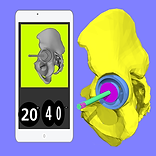
Hip Navi Pro R is Navigation software for Total hip arthroplasty leverages Apple Vision Pro’s to navigate but with registration of anatomical points of interest


Drill Navigator App leverages Apple Vision Pro’s advanced real-time hand tracking to deliver a precise visual overlay for drilling tasks. It displays the exact position, depth, and angle of the drill, allowing users to monitor orientation continuously and adjust effortlessly.With intuitive controls and a clear visual guide, the app transforms complex pathways into an easy, seamless, and accurate user experience.

Drill Navigator pro App leverages Apple Vision Pro’s advanced real-time hand tracking to deliver a precise visual overlay for drilling tasks. It displays the exact position, depth, and angle of the drill, by the use of special device reference object allowing users complex pathways into an easy, seamless, and accurate user experience.

NavigatorIMIvis mmersive Navigation for Distal Interlocking of Intramedullary Nails Using Apple Vision Pro

TouchSee CT Patient CT or MRI scans are processed into 3D models . By uploading to Apple Vision Pro doctor can use his finger to gently touch the surface of the patient’s skin and place overlaid detailed 3D structures — skin, bones, vessels — extracted from the patient’s CT or MRI scans directly onto the body in real time.

App In Augmented reality in iOS iPad iphone


how it works
Tools needed for Augmented reality Apps

Instruments that determine the exact spatial orientation act as dynamical reference and should be 3D-printed before using the app, by downloading the appropriate 3D files accordingly from developers site . Each instrument is recognised by separate dedicated attached QR-code images with different dedicated colour. Please feel free to ask to download the relevant files.
A built-in known dedicated QR-code image should be exported from the app by pressing the export button. The QR-code images are exported in photo library. After printing them in a common colour printer preferably as an adhesive label, then should to be attached firmly to each dedicated instrument for certain dedicated surface plane. Each one is dedicated for certain position. The dimension of the printed adhesive QR-code is dedicated for rectangular surface (4cm X 4cm). The printed QR-code image is intended to work as unique dedicated tracker respectively and should be in the visual field of iPhone’s camera. In details, each time the QR-code image is recognised inside the screen, a different colour sphere appears (red for pelvic device , magenta for pointer, green for femur , orange for operaion table) are assigned, appearing at the center of the rectangular image over the surface respectively, for each dedicated QR-code. The QR-code images are recognised continuously and tracked-by in real time by the App, as along as the top centred button is on (highlighted). The tracking system is the iPhone’s camera.
-The unsterilized i-Phone should be placed in a sterilized waterproof sealable bag. This is common practice in surgical fields where non sterile parts are usually placed in sterile bags like arthroscopes, cameras, optical wires, tools etc. Sterile bags are readily available in operation rooms, taking always in to account bag manufacturer specification and guidelines. Plastic coverage should be transparent and not blur the iPhone cameras.
-All devices could be sterilised according to manufacture guidelines (CE) for the 3D printed material specification used.
Pointer Tool.
A device dedicated for surface registration - should be 3D-printed. The other side of the rod is the side that acts as mechanical pointer tip locator.
The QR-code image (magenta) dedicated for the PT should also exported from the app by pressing the export button and printed in a common colour printer preferably as an adhesive label, and attached firmly to dedicated rectangular surface plane of pointer tool. The QR-code image marker is captured and recognised continuously in real time by the App and a magenta sphere appears over the center of the QR-code image. Once the QR-code image is recognised in Augmented reality view, a cylinder appears with two spheres at the edges: one proximal (magenta) appear over the center of the attached QR-code image over the dedicated rectangular surface, and second distally a red sphere appears over the tip of rod at the pointer tip in augmented reality (AR). Distal sphere should coincide with the tip and this should be corrected before registration by calibration.
Calibration is achieved by simply pressing the directions buttons (+,-) over the screen, thus the position (XYZ) of magenta tip sphere and the attached grey cylinder in augmented reality [magenta and red sphere are the edge of cylinder] are adjusted as whole construction accordingly. The user aim the pointer tip sphere in AR to be aligned in all dimensions and coincide over the mechanical pointer tip location of the rod of the PPT tool.
More specifically:
- By pressing the + or - button in the upper row, the (z) distance is adjusted respectively. It is recommended first to measure manually the distance from tip-pointer to case (by default this is 20 cm), and calibrate first the Z distance, which is the real distance from the magenta sphere on the center of the QR-image surface to tip of the pointer. The following x and y calibration procedure are in two dimension over the screens phone (x,y), aiming to bring the presented red sphere to coincide optically with actual pointer tip.
- In the intermediate row the + or - button adjust the (x) distance of magenta sphere.
- In the last row by pressing the + or - button the (y) distance magenta sphere is adjusted likewise.
Saw Adaptor
The SA helps to navigate the saw blade accurately. SA can be 3D-printed and inserted as an accessory to real saw blade. A QR-code image dedicated for the saw adaptor should be recognized by the App and is continuously tracked. Saw adaptor can be adapted over conventional saw orthopaedic blade and calibration is unnecessary as long as the distance between QR-code image and cutting edge saw is 26mm (Z axis).
The SA helps to determine the exact spatial orientation of saw blade aiding the accuracy of the oscillating Bone saw blade. Two perpendicular crossed rectangular planes appear (one blue horizontal, one vertical green) in AR. The crossing point of the planes is passing to the center of the saw blade. a hit sound is played confirming that direction of saw blades is the right according to planed.
Validator tool
Estimation of extension and flexion space is achieved by using the spacer which allow to assess the gap parallelism manually.The tool is a spacer, to measure the gap between the femur and the tibia in flexion and extension but carry a dedicated QR-code image (black). Once is recoconized a orange cylinder appears over the ridges of the tool perpendicular to the tool axis. The angle between transepicondylar line (blue) and the above mention orange cylinder allow to estimate the φ angle and likewise between the Femoral flexion axis (green) the BA angle - Balance angle.
During gap acquisition, the femur and the tibia assume a position that depend exclusively on ligament constraints by enabling the surgeon, together with the information provided by the software φ angle, to perform a navigated ligament balancing. Varus and valgus stress is applied near full extension and around 90 degrees of flexion to assess stability. Measured φ angle between tool and epicondylar axis in saggital plane depicts the laxity of knee if φ> 2 degrees then knee is lax.
Joint Liner tool
Useful for joint line registration and posterior condyles registration and looks like butterfly with tail where a qr code image is attached and a green there appears .
Pelvic reference device
Femur reference device
Insertion device (I)
Plane operation table registration device(PR)

The Clamp tool (CT). This tool is a simple clamp attached to the handle of the inserter or reamer that has a slot designed to receive perpendicular the pointer tip side of the case i-Phone-probe tool (CiPT).

Passive sensor (PS). This device is dedicated to act as dynamic reference array during tracking. Once 3D printed and added the adhesive QR-image label over the dedicated surface should be placed in a sterilized waterproof sealable bag and then it should firmly attached to bone or other anatomical landmark by the use of preferably to Swanz screw or a body of mini external fixator.


A built-in known dedicated QR-code Image should be exported from the app and printed in a common colour printer preferably as an adhesive label and attached firmly to passive sensor dedicated surface plane. The dimension of the printed adhesive QR-code Image Label should be four by four in centimetres in order to match perfectly the passive sensor dedicated surface. The printed QR Image is intended to work as unique dedicated tracker and should be in visual proximity. The QR-code Image marker is captured and recognised continuously in real time by the App. Over the printed QR-code Image marker in augmented reality, a red sphere and a green plane appear laying over the surface plane once the QR-code Image is recognised. The QR-code Image marker is constantly recognised and continuously tracked by the app as along as the top centred button is on - highlighted. The Passive Sensor (PS) should be firmly mounted on pelvic bone. The QR-code Image attached over PS acts as a dynamic reference base attached to the system. Prerequisite is visual contact through i-Phones screen of QR-code Image. The position of all future register points are updated continuously while the QR-code Image acts as a dynamic reference guide marker. In case the patient pelvis is placed in different position during surgery and the attached PS on patient pelvis move as a whole array. Accidental change of pelvis position intraopratively is common and the app updates the position of registered points in AR according to the new position of patient pelvis respectively. Aiming the iPhones camera to the PS QR-code image the app recognise the above mentioned image, recalculates the position of the already registered points in AR and updates accordingly their position in the right place over the real patients pelvis in the new position without the need to reregistering the points.


Disclaimer
Before you use the software. The software should be used only for educational purpose namely training Orthopaedic Residents etch. Never use in real Surgery regarding its plausibility, validation is pending. The app is for educational use. Clinical judgment and experience are required to properly use the software.These instructions alone do not replace in depth training in planning for osteotomies. It only serves as a general guideline. All information received from the software output must be reviewed before any actual attempt at lab i.e. cutting saw bone for training purpose! The App indicated for assisting during training the Operator. Judgment and experience are required to properly use the App. The software is not for primary image interpretation. Any influence to the operators in making decisions remains Surgeons own responsibility and experience. App does not dispense medical advice.